Meryam Sahin (talk | contribs) No edit summary |
Meryam Sahin (talk | contribs) m (username removed) (log details removed) |
||
(No difference)
| |||
Revision as of 10:53, 13 August 2026
Business Process Model and Notation (BPMN) is a standard for representing business processes graphically. BlueSpice provides a graphical editor for creating and editing BPMN diagrams. The editor is based on the open-source project bpmn.io. The Page Forms is used to facilitate the input of information for each element.
Open the BPMN editor
The BPMN editor can be opened from the following locations:
- Select Processes in the main navigation. On the Processes page, select Processes in the page tools panel. Administrators can deactivate the Processes entry in the Config Manager.
- Open Wiki actions and select Processes in the Overview section.
- Select the New content button in the header bar and select New process.
The BPMN editor opens after selecting one of these options.
Create a process diagram
All process pages are created in the Process namespace.
To create a process diagram:
- Enter a process name.
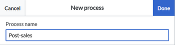
New process dialog. - Select Done. The BPMN editor opens with a start event already added.

The diagram must meet the minimum requirements before it can be saved.
Add shapes to the diagram
Each process diagram requires a start event and an end event. Additional shapes can be used to represent activities, decisions, data, participants, and other elements of the business process. The main BPMN elements are:
- Events: Represent something that happens during a process, such as a start or end event.
- Activities: Represent work performed as part of a process, mainly tasks.
- Gateways: Represent decision points and determine how process paths are split or merged.
If a BPMN symbol is unfamiliar, refer to the Camunda BPMN 2.0 Symbol Reference. Not all BPMN symbols are available in the BlueSpice BPMN editor. For example, expandable subprocesses cannot be added. To add a shape:
- Select the preceding shape.
- Select the required symbol to append the next shape.
Shapes can also be dragged from the toolbar onto the diagram.
Shape types
The following shape types are available in the BPMN editor:
| Shape | Description |
|---|---|
| Start event | Represents the trigger of a process. A start event has a single narrow border and can only be a catching event. It is therefore displayed with an open or outline icon. |
| Intermediate/boundary event | Represents an event that occurs during a process between activities. An intermediate or boundary event is shown with a thin double border. For example, a task can lead to an event that sends a message to another pool, where another event waits to receive the response before the process continues. |
| End event | Represents the result of a process. An end event has a thick border and can only be a throwing event. It is therefore displayed with a solid icon. |
| Gateway | Represents a decision point and determines how process paths are split or merged, depending on the defined conditions. |
| Task | Represents a single unit of work that cannot be broken down into a lower-level process activity. A task is the lowest-level activity shown in a process diagram. A set of tasks can represent a higher-level procedure. |
| Data object reference | Represents information used by a process, such as a document in physical or digital form. It is displayed as a page with a folded top-right corner. |
| Data store reference | Represents information that needs to be stored persistently. Data stores can represent IT systems and applications, as well as physical folders or archives. |
| Pool / participant | Represents a major participant in a process, such as an organization. A pool can contain one or more lanes. An open pool displays its internal details, while a collapsed pool hides the internal details. |
| Group | Groups activities visually without affecting the process flow. A group is an artifact represented by a rounded rectangle with a dashed border. |
Events represent something that happens, while activities represent something that is done. Events can be catching or throwing events, depending on whether they receive or trigger an event.
Data objects and data stores can be connected to process elements with a data association. Data associations show how process steps use data but are not part of the process flow.
Shape actions
When a shape is selected, the available actions are displayed.
| Action | Description |
|---|---|
| Append end event | Adds an end event with a connector after the selected shape. |
| Append gateway | Adds a gateway with a connector after the selected shape. |
| Append task | Adds a task with a connector after the selected shape. |
| Append intermediate/boundary event | Adds an intermediate or boundary event with a connector after the selected shape. |
| Add text annotation | Adds an annotation to the shape. The annotation line and bounding box can be resized and repositioned. |
| Change element | Changes the shape to a more specific shape type. |
| Delete | Deletes the shape. |
| Set color | Changes the fill color of the shape. For line objects, the outline color is changed. |
| Connect to other element | Connects the selected shape to an existing shape. This action is only available when an endpoint for the connection exists. |
Editor tools
The toolbar provides tools for working with the diagram. Hover over a tool to display its name.

| Tool | Description |
|---|---|
| Hand tool | Allows navigation across the canvas without accidentally moving elements. |
| Lasso tool | Selects multiple shapes at the same time. An object is selected only if the entire object is within the selection. Hold the Shift key to add or remove individual objects from the selection. |
| Create/remove space tool | Adds or removes horizontal or vertical space in the diagram. |
| Global connect tool | Connects a shape to a distant shape. The tool is automatically deactivated after creating the connection and must be selected again for another connection. |
If an action does not produce the intended result, press Ctrl + Z to undo the changes.
Validate and save the diagram
A diagram must meet the following requirements before it can be saved:
- A start event is present.
- An end event is present.
- Every shape that generates a wiki page has a unique label.
If the diagram cannot be saved, select the Toggle linting overlays button to display errors and warnings. The affected elements are highlighted in the diagram.
Correct the reported issues and select Save changes to save the diagram.
During the save process, a dialog provides the option to create wiki pages for the relevant process elements. These pages can also be created later.
Unique label requirements
The label of an event or task is used to create its associated wiki page. Therefore, each event and task that generates a wiki page requires a unique label within the process.
Gateways and other shapes that do not generate wiki pages do not require unique labels. For example, the same Yes or No label can be used for multiple gateways in a diagram.
Rename a shape
To rename a shape:
- Double-click the shape.
- Change the label.
- Save the diagram.
If a shape with the same name already exists, BlueSpice automatically adds a number to the new name to make it unique.
If the shape already has an associated wiki page, renaming the shape also renames the associated page.
Create wiki pages for process elements
Description pages can be created for process elements when the diagram is saved. To create description pages:
- In the save dialog, select the checkbox for creating description pages.
- Complete the save process.
- Review the list of created pages in the confirmation dialog.
Description pages are created for start and end events and for the different task types, such as user tasks and script tasks. A Call activity does not create a description page.
After the pages are created, the corresponding shapes in the diagram become interactive and link to their description pages. Select a shape to open its page.
Each description page contains information about the process element:
| Element | Description |
|---|---|
| Breadcrumb | Shows the location of the description page as a subpage of the process page. |
| Incoming connections | Lists the connections that precede the process element. |
| Outgoing connections | Lists the connections that follow the process element. |
| Page flow | Provides links to the preceding and succeeding description pages. |
| BPMN task description | Provides a placeholder for a custom description. Edit the page to replace the placeholder with the required content. Once content has been added, the placeholder template can be removed. |
Embed a process diagram in a wiki page
BPMN diagrams are created and edited in the Process namespace. Existing diagrams can be embedded on any wiki page. To embed a process diagram:
- Open the page in the VisualEditor.
- Open the Content droplets menu in the editor toolbar.
- Search for process.
- Select the Process content droplet.
- Select Insert.
- Enter the name of the process.
- Select Save.
The embedded diagram can include a toolbar with additional options if the toolbar toggle is enabled.
| Option | Description |
|---|---|
| Go to the diagram page | Opens the process page where the diagram can be edited. |
| Download diagram as SVG | Downloads a copy of the diagram in SVG format. |
| Center diagram | Centers the diagram in the display. This is useful for large diagrams that require repositioning while viewing. |
| Show raw XML | Displays the XML source of the diagram. |
| Show diagram | Returns from the XML source to the diagram. |
Limitations and special considerations
The following limitations apply when working with BPMN diagrams:
- Process and activity page names: Wiki page titles are limited to approximately 255 characters. Very long process names combined with long activity or swim lane names can cause errors when activity pages are created.
- Slashes in activity names: Slashes (/) are not permitted in activity names because they are used to create the subpage path.
- Subprocesses: Expandable subprocesses cannot be created in the BPMN editor. A call activity can be created, but it does not create a description page.
- Description pages: Wiki pages are only created for the supported activity types. Switching to a special activity type, such as a manual activity, does not create a description page.